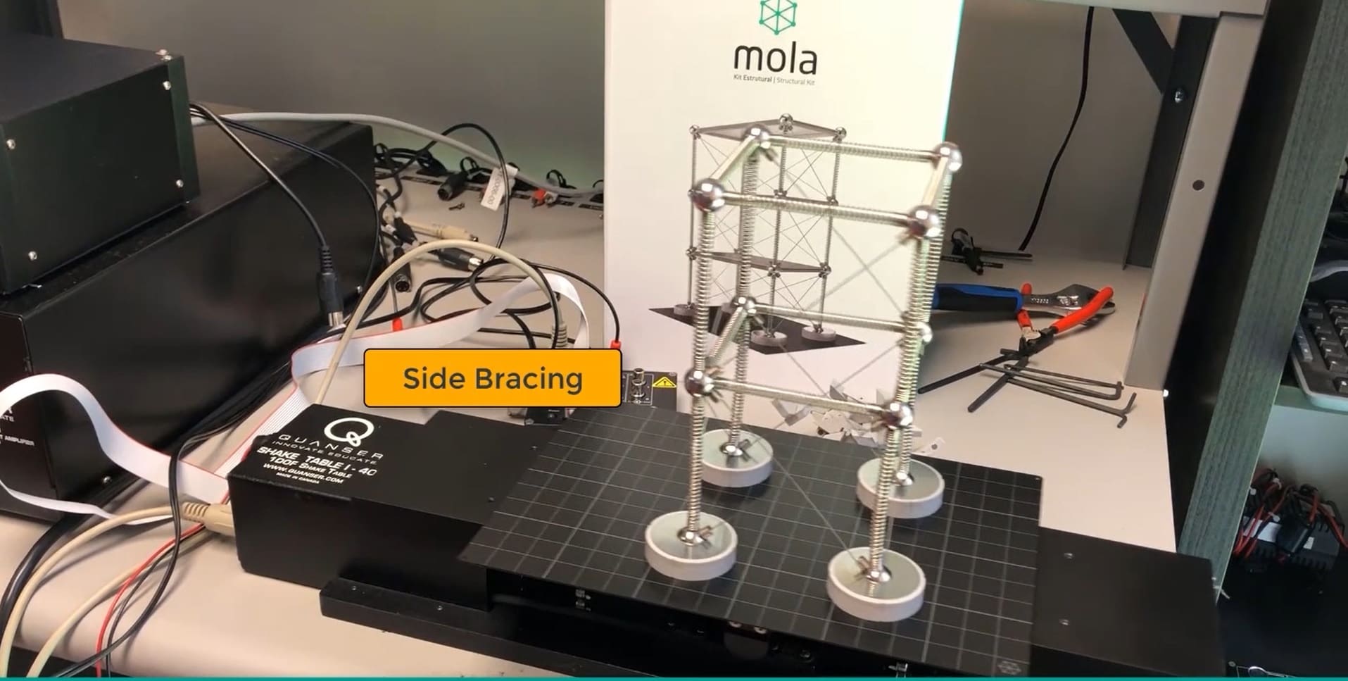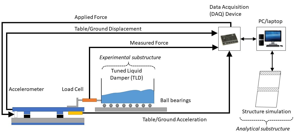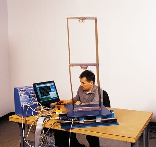
If you were on the top floor of a tall building on a windy day, did you get that feeling the building is swaying? High winds can cause tall structures to swing or deflect. If you did not notice anything, it might mean the building’s design included some sort of the structural motion control method. Structural engineers employ various systems and techniques to compensate for the motion of the building. In this post, I take a closer look at mass dampers, specifically, the Translational Tuned Mass Dampers (TMD).
What is a Translational Tuned Mass Damper?
A tuned mass damper (TMD) is a mass-spring-damper system that is designed to attenuate the motions of a structure. The TMD is tuned to a particular structural frequency (typically to the first natural frequency of the structure). When this frequency is excited, the damper resonates out of phase with the motion of the structure. The damper’s inertia force acts on the structure, dissipating the energy. Interestingly, the concept of TMD was first applied in ships. In 1909, Hermann Frahm, German shipbuilding engineer introduced TMDs to reduce the rolling motion and hull vibrations.
 A translational TMD is a type of tuned mass damper where the mass moves laterally relative to the floor. An example of a real-life application of translational TMDs is the John Hancock Tower in Boston, Massachusetts. LeMessurier designed a dual translational mass damper system, with one 275-ton mass damper installed at each end of the 58th floor of the building. As Connor and Laflamme describe in Structural Motion Engineering (2014), each damper is a large lead-filled steel box with dimensions 5.2 x 5.2 x 1 m, riding on a 9 m track. The mass is fitted with hydraulic dampers that are enabled when the floor acceleration exceeds 0.003 g. This solution proved to be a very effective method reducing the motion of the building by 40% to 50%.
Explore Translational Tuned Mass Damper in the Lab
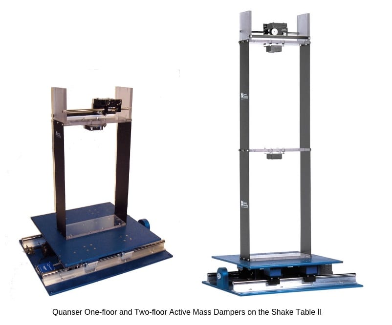 The tuned mass damper concepts are typically covered in the structural dynamics and earthquake engineering programs curricula. To demonstrate these concepts – and explore them further, many institutions around the world use Quanser Active Mass Damper systems.
A linear motorized cart mounted on the top of the building-like structure emulates a translational TMD system. Using the accelerometer readings, the cart dampens the motions of the structure by moving back-and-forth. The figure below shows the dynamics of a one-floor Active Mass Damper.
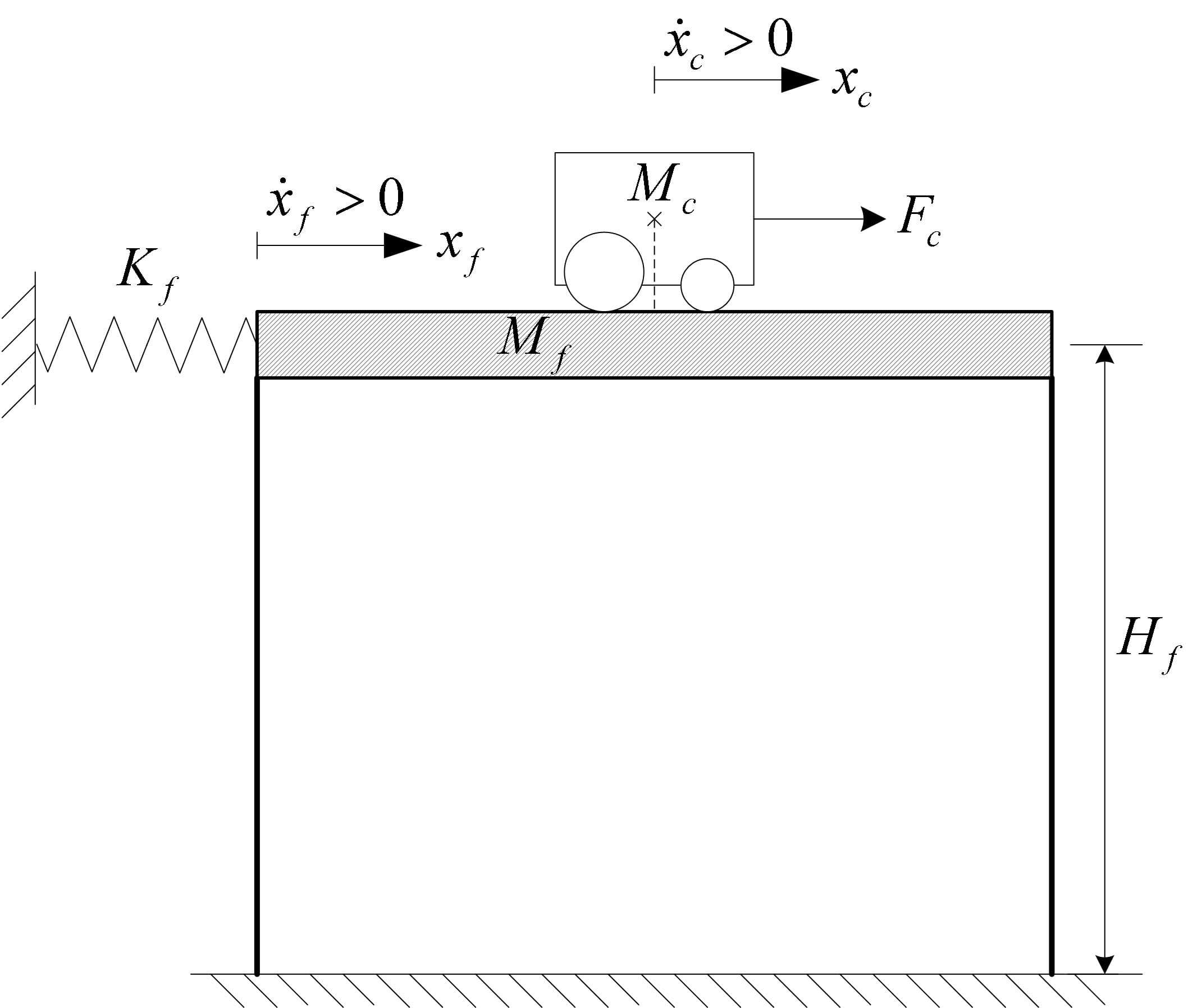
After deriving the linear equations of motion, a state-space model is defined:
![]()
Where the state and output vectors are defined as
![]()
and
![]()
The cart position, measured by an encoder, is denoted as xc(t) and the estimated displacement of the top floor relative to the ground is xf(t). The output vector, y, includes the measured variables of the structure: the position of the cart (encoder) and the acceleration of the top floor (accelerometer).
In order for the cart to compensate for the motions of the building, the displacement of the floor relative to the ground (or in this case, the shake table) needs to be known. However, there is no sensor that directly measures the xf(t) displacement of the top floor. As a result, the displacement has to be estimated using the available measurements (i.e., cart position and floor acceleration).
One approach is to design a full-order observer design to estimate the floor displacement and then use a state-feedback control to minimize the deflection of the structure (i.e., by moving the cart accordingly). The structure of the full-order observer is of the form:
![]()
and
![]()
The estimated state and output vectors from the observer are denoted x0 and y0. The estimation error is defined as:
![]()
The control input for the state-feedback is the voltage applied to the DC motor on the linear cart:
![]()
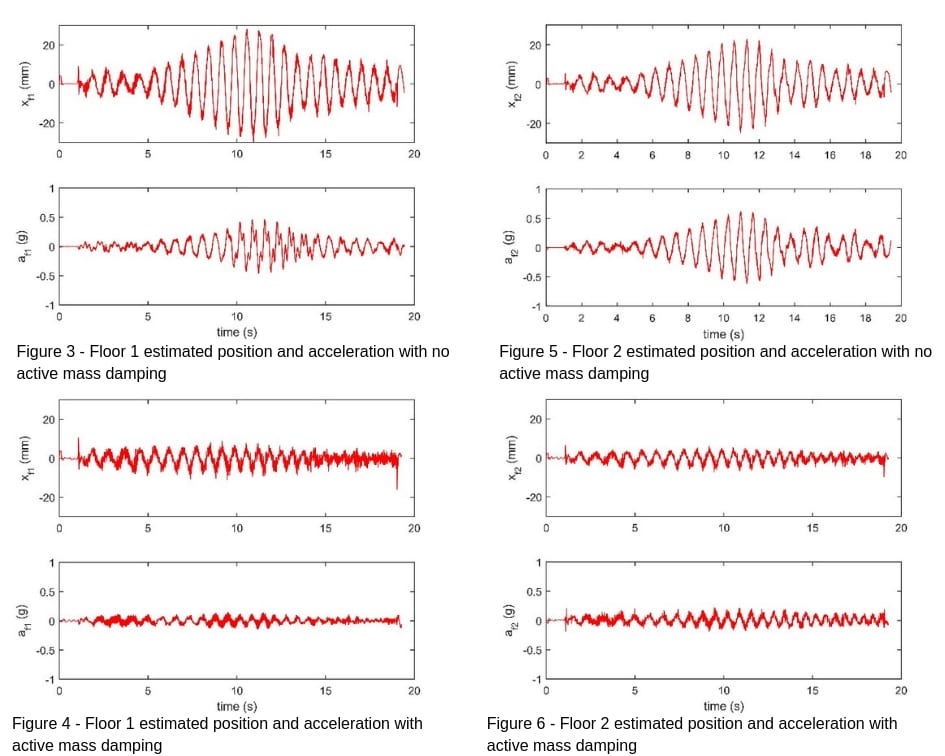
The state-feedback controller gain K is computed using the Linear Quadratic Regular (LQR) optimization method with the derived state-space model. The results shown below are for the Two-Floor Active Mass Damper system (AMD02). The estimated floor deflection and measured acceleration of floor 1 and floor 2 is shown in Figure 3 and Figure 5 when no active mass damping is used. Figure 4 and Figure 6 results show the response when using active compensation. Note how both the estimated position and measured acceleration of each floor are reduced when the cart damping is turned on.
Other Active Mass Damping Strategies
There are various other ways to do active mass damping. Here are a few observer and control schemes implemented by various researchers:
- Deflection Control of Two-Floors Structure Against Northridge Earthquake by Using PI Controlled Active Mass Damping (Tinkir, Kalyoncu & Sahin, 2013)
- Experimental Comparison of Dynamic Behavior of Structures with a Particle Damper and a Tuned Mass Damper (Lu, Huang, Wang & Zhou, 2018)
- An active mass damper system for structural control using real-time wireless sensors (Casciati, Chen, 2012)
- Control Structure Interaction of Electromagnetic Mass Damper System for Structural Vibration Control (Zhang, Ou, 2008).
- Simulation and experimental tests on active mass damper control system based on Model Reference Adaptive Control algorithm (Tu, Lin, Tu, Xu & Tan, 2014).
- H-infinity robust control design of active structural vibration suppression using an active mass damper (Huo, Song, Li & Grigoriadis, 2008).
- Control strategies and experimental verifications of the electromagnetic mass damper system for structural vibration control (Zhang, Ou, 2008).
You can find more research papers in our online collection.


